
Pre-amplifier circuit

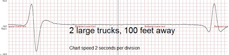
This circuit is sensitive enough to detect cars and trucks going on a road up to 100 feet away, when used with our ELF Antennas, STORMWISE Part MU22-01H-15H-BC or MU22-005-10H-BC.
The circuit also will detect local earthquakes, and geomagnetic storms.
Uses common standard parts values, parts are available from Radio Shack or other electronic part stores.
Study all the photos and the above circuit diagram carefully. There is more than enough info on this page to aid you in a successful build that will work from the first try.
If your data logger instrument is not sensitive enough in the ELF range, then you can add the extra gain required by using a simple two transistor pre amplifier.
Just want to detect the big quake that affects your area? Then don't use any magnet in your seismograph. The ground motion through earth's magnetic field will be enough for detection of local ground motion.
Connect any data logging millivolt meter or oscilloscope to the output of this ELF Amplifier to see extremely slow waveforms. See www.dataq.com for PC data logging instruments. If you want to see clear seismic waveforms below 1 Hz you need a 13 bit or higher resolution data logger. The 8 bit or 10 bit units make slow seismic waveforms look like static.
If using the DATAQ PC recording software, set sample rate at 20 samples per second. This gives excellent waveform resolution at 10 Hz and lower. Set chart scroll rate (chart compression) at 5 seconds per division.
Parts list: All parts are available from Radio Shack Stores, except for the Seismograph Antenna.
Parts list tested and optimised for both listed transistor parts.
Antenna: STORMWISE Part MU22-01H-15H-BC or MU22-005H-10H-BC or any Stormwise ELF Antenna for use below 30 Hz.
2 and 1/8 inch Modular IC BREADBOARD SOCKET (base with holes circuit is built on) Radio Shack Catalog number 276-003.
JUMPER WIRE KIT: Radio Shack catalog number 276-173. Color coded wire kit for use with above socket.
Q1 = 2N3904 or 2N4401 NPN transistor.
Q2 = 2N3904 or 2N4401 NPN transistor.
IMPORTANT NOTE: Test each transistor's hFE value with a transistor tester, hFE gain value must be greater than 200, but not greater than 300. If greater than 300 then you will find that some transistor junction flicker noise (random ELF waves below 0.5 Hz) may be introduced by the transistor itself.
IMPORTANT NOTE: With the pre-amplifier circuit working and placed in a box to keep air currents off of the transistors, and the antenna connections shorted with a jumper wire you should see only a solid flat line on your screen or chart recorder. There should be no wiggles in the line when the antenna is shorted with a jumper. You should consider NPN transistors with hFE gains above 300 as 'defective' for use in this seismograph application.
NOTE: An inexpensive Multi-Test Meter (Radio Shack has these) can be used to test transistors, some models feature a transistor hFE gain test function.
D1 = 1N914 or 1N4148 silicon diode. (protects input transistor from negative static discharge). Wire polarity like shown.
D2 = 1N914 or 1N4148 silicon diode. (protects input transistor from positive static discharge). Wire polarity like shown.
R1 = 1 Meg-ohm resistor.
R2 = 1 K-ohm resistor.
R3 = 1 Meg-ohm resistor.
R4 = 47 K-ohm resistor. (was 10 K. Changed on May 25, 2017).
R5 = 1 Meg-ohm resistor.
R6 = 47 K-ohm resistor. (was 10 K. Changed on May 25, 2017).
R7 = 47 K-ohm resistor. (was 10 K. Changed on May 25, 2017).
Electrolytic capacitors have a voltage polarity marked on them. It is important to install them correctly or else circuit will not work.
C1 = 10 uF Also see tuning info for the ELF antenna.
C2 = 470 uF electrolytic capacitor (was 220 uF. Changed on May 25, 2017).
C3 = 0.22 uF polyester film capacitor. (limits the high frequency response to 10 Hz by using negative feedback).
C4 = 1000 uF electrolytic capacitor.
C5 = 0.22 uF polyester film capacitor. (limits the high frequency response to 10 Hz by using negative feedback).
C6 = 4700 uF electrolytic capacitor.
C7 = 1000 uF electrolytic capacitor. (Prevents scratchy contact noise from battery leads and random impulse noise from battery discharge process).
NOTE: C3 and C5 values shown limit the high frequency response of the circuit. This prevents power line hum from being detected, as well as RFI. Value shown 0.22 uF cuts off at 10 Hz. An 0.1 uF capacitor will move the cut off up to 20 Hz. 0.047 uF will move it up to 40 Hz.
IMPORTANT NOTE: C2, C4, C6 if -- NOT -- interested in detecting down to 0.03 Hz, change these values to 100 uF. This will allow circuit to start up sooner. Else you have to wait about 4 minutes from first turned on while capacitors charge up.


Click Here for More Photos of the ELF amplifier.
Don't miss the small bare wire jumpers in the photo. One is near "G" (at the left in photo) and the other is just a few steps to the right just under the 100 uF capacitor.

When first powered up, allow up to 3 minutes for the circuit to begin working and your data reading to stabilize. The capacitors need time to charge up fully, this takes about 3 minutes.
When first powered up, the output will be go from a positive level to a negative level then come back up to near zero volts out.
NOTE: If you are not interested in detecting sub 1 Hz waves, change C2 to 100 uF, C4 to 100 uF and C6 to 1000 uF. This will speed up the start up time when first powered up.
IMPORTANT NOTE: Test each transistor's hFE value with a transistor tester, hFE gain value must be greater than 200, but not greater than 300. If greater than 300 then you will find that some transistor junction flicker noise (random ELF waves below 0.5 Hz) may be introduced by the transistor itself.
IMPORTANT NOTE: With the ELF Amplifier Circuit working and placed in a box to keep air currents off of the transistors, and the antenna connections shorted with a jumper wire you should see only a solid flat line on your screen or chart recorder. There should be no wiggles in the line when the antenna is shorted with a jumper. You should consider NPN transistors with hFE gains above 300 as 'defective' for use in this seismograph application.
FINISH IT UP!

Notice how the binding posts are attached inside the box in the photo above. The (weak) lock washers that came with them were not used! Rather a stepped drill bit was used to drill the aluminum, which tends to melt it slightly during drilling. At first it will look like your're making a mess of the holes as it forms an ugly melted burr on the inside. Don't worry! When you bolt the binding post down to this ugly burr that forms it makes a built in lock washer in the aluminum box that holds far tighter than the one supplied with the binding posts. Just remember to drill the box from the outside else the burr will be on the outside instead of inside the box.
The only soldering needed is the wires on the binding posts, like shown. If you can't solder other methods are available for connections such as terminal posts.

The unit MUST be enclosed in a sealed project box of some type like shown above, to prevent thermal detection of room air currents blowing across the transistors. Try blowing on the transistors from 2 feet away, they will actually detect the sudden change of the air temperature from your breath. Enclosing the circuit in a sealed box completely stops this effect from happening. Slow normal room temperature changes do not affect the circuit when it is enclosed in a box.
This ELF Amplifier Circuit will work with the DATAQ data logger at www.dataq.com or other data loggers which require a pre-amp for low level signals.
Too much sensitivity for your data logger? Change R2 to a higher value. Try 10 K-ohms to reduce level @ 5 times.
The ELF Amplifier Circuit draws 1 milliamp at 9 volts. A pocket radio draws about 30 milliamps for comparison. A 9 volt NiMH battery will power the pre-amplifier for about 1 week before needing recharge.
For much longer run time you can use 6 "D" cell batteries, ( 9 volts total ) which will power it much longer than a small 9-volt NiMH battery. You can also use a 6-volt 4 amp-hour rechargeable "lantern" battery like the type used in deer feeders or in 6 volt emergency lighting. This type of rechargeable battery will power the unit for 2 months. Recharge the battery per the manufacturer's instructions with approved charger.
It has been observed that 9-volt NiMH batteries will quickly drop to a useless voltage level when needing to be recharged.
It is important to keep your battery fully charged as the output signal swing level (with this pre-amplifier shown) is dependant on battery voltage level. If you want to compare signal levels from different earthquakes you MUST have a stable battery voltage over time.
RECORDING SOFTWARE AND HARDWARE from www.dataq.com.
DATAQ SOFTWARE AND HARDWARE (13 bit data resolution. Best unit, higher signal gain.)
DATAQ SOFTWARE AND HARDWARE (8 bit data resolution. Inexpensive PC data logger.)