You can easily build a working AM radio!
We will be showing how to build a new 2016 version of this AM radio, using only 3 transistors or 5 if you add the signal meter. ( come back when link is added here ).
You can amaze yourself and your friends by building a working AM radio! There is a special pride in saying "I built it myself"!
If you have never built a radio before then just start from "scratch" here! There are no tricky adjustments to worry about. You don't need any special test equipment to get it working.
The radio produces loud volume from its powerful transistor audio amplifier. Drives a speaker loudly!
Remember or discover the 'old days' when radios were -VERY LARGE - and had that "open AM sound quality" which only AM radio can give! Now you can build your own table radio, or even go up scale to a full-sized console cabinet model with room-filling sound!
This very nice AM portable radio can be built from just a handful of parts.This radio will pick up stations loudly without needing any external antenna or ground connections, the sole antenna being the wire wound on the ferrite rod. Station selectivity is refreshingly good for this type of radio as "Q" runs extremely high and separation of adjacent stations 30 KHz apart is pretty good for this type of radio.
Listen to local stations by day and at night you will hear AM stations from all over the USA without any other antenna than the built-in ferrite rod antenna.
This radio is what is called a "TRF" Receiver, or Tuned Radio Frequency Receiver. It is an amplified "crystal" radio. All amplification is done at the received signal frequency with a single RF pre-amp stage. It does not use any IF (intermediate frequency) amplifiers or RF mixers like modern "super-heterodyne" receivers.
The radio is not a tricky noise-producing "regenerative" unit.
This amplified crystal radio receiver does not generate or produce RFI energy.
The challenge was to make a great AM radio but without using the tricky frequency-conversion circuits or regenerative circuits (or any other circuit that generates radio energy) that are impossible to align without skill and test equipment. The great news is that you can build this radio even if you're new to electronics.
This radio is very similar to some antique AM pocket transistor radios that were produced. Some early AM pocket transistor radio manufacturers boasted about their product having just two transistors! This radio has 5 transistors and a much larger antenna so it will perform so much better than those ever did!
Because this radio does not have any noise-blankers or automatic gain controls (AGC) you get the pure effect of "open-sounding AM" the way it used to be (and always should be)! At night you will hear the fading AM stations and occasional distant lightning static just like your grand-pa used to hear with his AM radio! Build this AM radio and bring back that "good ol' sound" from the good ol' days!
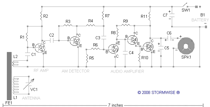
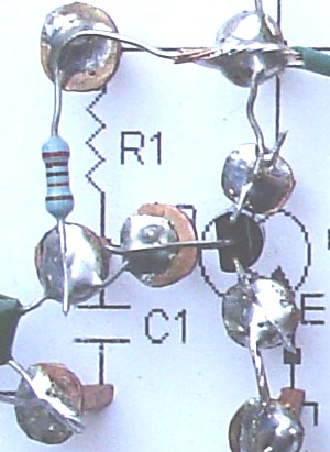
The different functional sections of the radio are shown on the circuit template. The radio picks up stations with the tuned ferrite rod antenna (FE-1, L1, L2) and feeds them to a radio signal pre-amplifier transistor (Q1). The radio's RF-amplifier feeds the signal to a transistor audio detector (Q2) that pulls the audio off the radio wave. Transistor Q2 is biased in such a way that it works both as an AM detector and audio pre-amplifier. The audio signal (voice, music) coming out of Q2 is fed to a transistor audio amplifier that boosts it enough to drive a speaker to loud room-filling volume.
By successfully building this radio you will learn how basic electronic circuits work and how AM radios work. We've kept it simple using only transistors and individual parts to allow you to learn how basic electronic parts work. The design is simple yet delivers room-filling sound from local stations and at night from distant stations. The radio will receive loudly a typical 250 watt local AM station 15 miles away, as an example of daytime sensitivity. After dark, strong AM stations from all over the USA come in loudly.
There is no volume control shown, but you can add one if you want to. Strong local stations come in very loudly, weak stations come in at lower volume. You can control the volume on loud stations by tuning slightly off-channel. We chose not to add a volume control as the radio produces good average volume on most stations.
The radio does not have an automatic gain control so radio fading can be easily heard, as well as making the radio very useful for experimentally listening to natural radio emissions such as lightning. This is radio as it "used to be" before all the automatic noise blanker features!
Printing the circuit diagram: right click and select "print". Or you can use "Photo Impression" software.
Printing tips: Some photo programs allow you to set the print height and width: The image width should be set at 7.3 inches. The image height should be set at 3.8 inches. The resolution should be around 96 dpi.
Do NOT darken the circuit diagram lines. The image will print looking gray. This is required for correct operation. The ink used in most computer printers is electrically conductive and will adversely affect circuit operation if you were to darken the ink lines. The image prints in gray so that microscopic dots form, keeping the printed image from being electrically part of the circuit.
The image contains a ruler reference that should be 7 inches long when printed to exact size.
You want your radio to look good so if you take your time, it may take up to 5 to 7 days working an hour at a time to finish the radio completely.
Enjoy the building part of it no matter how long it takes you!
To build the radio circuit on the copper tacks or copper weather strip nails (see photo below), a 15 watt soldering iron is what you need, unless using wire-wrap methods.
If you use copper plated weather strip nails, the size of the nails is called "3/4 X 17".
IF YOU CAN'T SOLDER, OR NEVER HAVE, (and don't want to learn how today...), Radio Shack stores have "perforated circuit board" and wire-wrap parts. You can build the radio without needing to solder anything. We did build the radio firstly on a solderless breadboard (just to fool around with it before permanently wiring it) and it worked fine even with the stray capacitance of the metal base. It did not squeal or oscillate even when built in such a "poor way" just for testing.
If soldering, use eye protection goggles (solder or the solder's hot wet flux can splatter). Open a window and use fan ventilation - solder fumes are poison says the fine print. Read all warnings.
Print out the above circuit diagram template. It should print out to 7 inches wide. A built in scale is shown for accuracy if you need to scale it for size on your printer.
Construction is done by using simple materials
The radio circuit itself can easily be constructed on a piece of dry wood. The dots show where to hammer in the copper tacks.
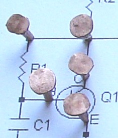
For our radio we placed the printed paper circuit card onto a small wooden craft plaque of 5 inches by 7 inches, and hammered in all the copper tacks.
Just hammer a copper tack (available from any local hardware store) in each dot in the diagram and solder the parts together.
Mounting the Resistors:
Place all the resistors first.
All resistors are rated at 0.25 watt (1/4th watt), except for R11 which is rated at 1/2 watt.
Mounting the Capacitors:
Place all the capacitors secondly. Some capacitors have (-) and (+) markings. Install these correctly else the radio will not work.
Mounting the tuning capacitor:
We used hotmelt glue to attach the tuning capacitor to the wooden box. Be careful to not get hot melt glue into the capacitor's fins, else you will have a mess!
Place all the other wiring thirdly.
Mounting the Transistors:
Place transistors lastly to prevent static or heat damage.
Transistors: Q1, Q2, Q4, Q5 are 2N4124 NPN small signal Transistors. (2N3904 NPN transistors will also work).
Transistor: Q3 is a 2N3906 PNP small signal Transistor.
Though the photos show the transistors placed "upside down", it is possible to place them right side up with full leg lengths. This makes them so much easier to remove if repair ever needs to be done. (Transistors are just about the only part in the radio that can be "blown out"). Just make sure that the E-B-C leads go to the right connections.
Winding the Coils on the Ferrite Rod:
There are several options for the ferrite rod:
For narrow band reception FE1 is Stormwise part # R623-2661102002-11. This is an 11 inch long by 1.02 inch diameter 125u ferrite rod. Shorter rods ( our 6 inch size ) will also work but give less sensitivity.
If you will be converting the radio to receive the Long Wave Band (150 KHz - 530 KHz) use Stormwise part # R623-43102002-11 800u rod instead of the 125u rod and just add more turns. 800u will receive both the AM band and the Long Wave band.
The 2000u "T" type rods are not suitable for this receiver.
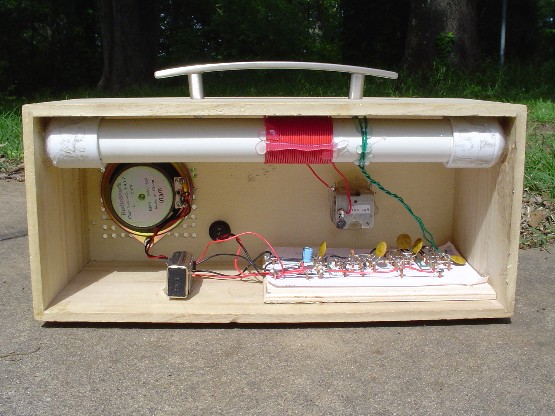
L1 is 37 turns of no 22 insulated stranded hookup wire centered on the ferrite rod. See photo above for placement.
L1 does not connect to chassis ground, it “floats” as shown in the circuit diagram and photos.
If not done already, mount and connect 384 pF variable capacitor to L1. Set capacitor for maximum (384 pF value).
To set the tuning span when radio is working: Tune to a local station on 530 KHz or 540 KHz. (You'll need another working AM radio to verify frequency). Adjust L1 windings by sliding a few turns on the end of L1 so space is between them to center the station on the tuning dial setting. After this setting is made, tune to a station near 1700 KHz at the top of the AM band. Setting the low end frequency should have automatically set the top high frequency to near 1710 KHz.
Adjustment for best reception your favorite station: If your favorite station is near the top of the AM band, for example 1580 KHz, and if you don't want to receive other stations, then adjust L1 number of turns (use less turns) so that your favorite station is tuned with the tuning capacitor set at 50% value or the center of dial mark setting. If your favorite station is near the bottom of the AM band, for example 750 KHz, then adjust L1 so tuning capacitor setting of 90 % value tunes the station.
Idea for push-button tuningFavorite stations can be tuned by simply using a rotary selector switch or separate pushbutton switches to place the correct fixed-value capacitor values across L1 for tuning your favorite stations without using a variable capacitor. Have fun experimenting.
Make sure that L1 is away from metal parts and away from the speaker.
L2 is 2 turns of no 22 insulated stranded hookup wire placed 1 inch away from L1. You can experiment with the number of turns here. Less turns (1 turn ) gives lower sensitivity but a narrower bandwidth. 3 turns gives more sensitivity and wider bandwidth. If you use 4 turns will give even more sensitivity but at the expense of station selectivity or the ability to separate neighboring stations on the dial.
L2 should be 2 inches away from L1, to maintain highest sensitivity and narrow bandwidth to prevent reception of two or more stations at the same time. Wind L2 on the side away from the speaker and audio section.
Keep the ferrite rod away from the speaker's strong magnet and away from the audio amplifier section to prevent squealing.
Speaker: Any 4-ohm, 8-ohm, or 16-ohm speaker.
DO NOT USE HEADPHONES OR EARPHONES! LOUD SOUND!!!!!!!!!!!!!!!!
Speakers of 16 ohms will work best (you can place two 8-ohm speakers in series). We chose to use Radio Shack part # 40-1417 which is a 3.5 inch car speaker with built-in cloth screen grille. Found it on sale. Probably obsolete. Frequency response 300 Hz - 10000 Hz. 5 watts RMS. Even though it is a 4 ohm speaker, it works great.
Choosing a speaker for your radio: We recommend any speaker of 3 inches to 8 inches. AM stations do not transmit any musical contant above 5000 Hz, so your speaker just needs to go up to 5000 Hz. Large speakers will create louder sound and give the radio a rich BASS tone. Speakers for 300 Hz to 5000 Hz are called "midrange" speakers.
Want a little more BASS from the radio? Change the speaker capacitor "C6" to double the value listed on the parts list.
The radio's audio amplifier will reproduce sounds between 20 Hz to 10 KHz.
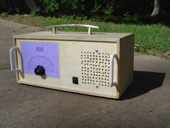
The radio circuit is placed into a wooden box (we bought the box in the craft department at Wal-Mart). We have added front-panel tuning knob and ON/OFF switch and loud speaker.
The finished table AM radio with carry handle (handle found at a hardware store) gives it an antique flare.
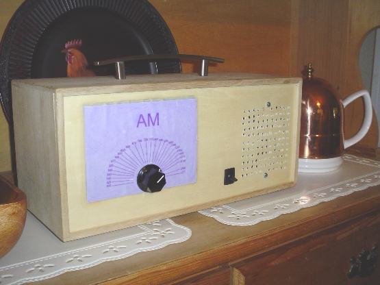
The radio works great and looks good. Make sure to place a back cover on the radio.
We had not yet added the front panel decorative handles (see them in other photos) at the time this photo was snapped.
We calibrated the tuning dial by tuning the radio's tuning knob and allowing the signal to peak on a nearby digitally tuned AM radio from the "tuned ferrite-rod antenna effect".
The calibration sheet was pulled off and scanned into a computer, then loaded into a photo/paint program and re-touched and re-drawn.
The new dial was printed on card-stock and was glued down using Elmer's glue, and it was also coated on the front with Elmer's glue which will slightly smear the ink-jet print to make it look more "antique-ish".
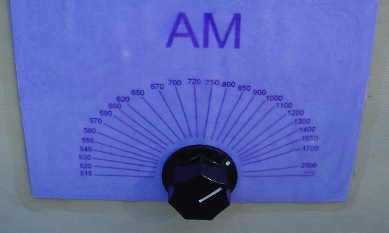
You will have to print and make your own tuning dial out of card-stock or an ink-jet printable transparency sheet, or just use a fine pen or other instrument and hand-mark the wood directly!
Perhaps your grandparents or great-grandparents built their own radio during the early days of radio. Now you can do it too!
You can printout and use this dial display on your homemade radio:
Scroll over to the right because it is large! Right-click and print picture. It is the right size to print out and use on your radio, (you can use a photo program to print it the correct size without loss of details. Just use the photo printing size adjustment in your photo software. Do not edit or crop the image down smaller. Loss of detail will result). Use this image if you don't want to hand-calibrate it yourself. The numbers may not match your radio's tuning range exactly.
You can also use wood-burning craft art calligraphy techniques to create your AM dial. This will produce a really cool label-less front panel. You'll need a wood burning calligraphy kit from a hobby arts and crafts shop.
Click Here to view the AM dial front panel you can print out and use.
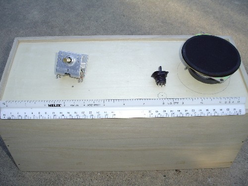
The wooden box with drill points marked. From left to right: Tuning capacitor, ON/OFF switch, Speaker.
We first considered drilling out the large circle for the 3-inch speaker to fit directly into, but thought it better to design a grill template and drill many small holes to act as a grill for the speaker.
Wal-Mart no longer has these wooden boxes!!?!! Try a craft store like Michaels. Or just build your own box out of wood and hot melt glue and some small nails. Make sure the front panel wood is thin enough so the front panel parts will mount through it correctly.
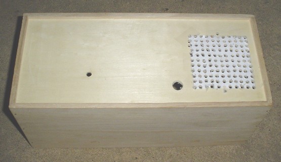
The holes are drilled. The paper speaker hole template (see below) that we made was placed and the holes are drilled out. Don't forget to drill the 2 holes to mount the speaker, and make sure that the mounting holes are not too close to any other drilled holes lest the speaker could come dislodged.
When powered up, the radio should draw approximately the current level listed above.
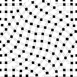
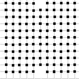
Here are two designs for speaker grilles. We drilled through the front panel wood and mounted the speaker behind the grill. Takes a lot of time to drill the holes but its better than cutting out a large circular hole to mount the speaker.
We used the square design.
You may choose to use your own design you make on a paint program on your computer. Make sure the grille is big enough for your speaker and that you have a minimum of 100 holes for the sound to go through.
Make sure to put a back cover on your radio and drill a few holes in the cover so the sound can come out the back too. This makes the radio's volume even louder and adds "richer" bass tones. You may want to experiment with different back covers and sound port-holes or speaker mounting or sound wave-guides to get the exact "custom" sound you want. Its your radio. Build it how you like it!
To build a full-size floor model just as big in size and sound as the early radios of the 1940's were of course!!!
We had no trouble building the radio. The radio worked from the start without any squeeling, hissing, or other electrical problems.
Start with a brand new 9-volt battery. As battery ages the volume will become lower so start out with a fresh battery!
You can check the various stages of the radio as follows:
Touching C1 if the L2 coil is NOT connected will produce a loud buzzing sound. This is normal, but will never occur once the L2 winding is connected. The front-end is in working order!
Touching C2 causes a buzzing noise from audio hum. This is normal. The radio's RF section works.
Touching C3 causes a buzzing noise from audio hum. This is normal. The radio's detector section works.
The audio amplifier requires use of the resistor and capacitor values listed, else it will not work correctly.
There are both PNP and NPN transistors used in the radio. Make sure you carefully place the "E", "B", and "C" leads of the transistor types to the correct tack points of the circuit diagram. Don't mix up your transistors!
Strong local stations may cause overload or background reception. Rotate radio to null out the strong station. The zero-point null is sharp.
Do NOT ground the L1 coil to the ground buss. Let the L1 coil "float" as shown.
Make sure to wind the L1 and L2 coils as shown in the photos. Make sure that the tuning capacitor's metal frame is connected to the end of L1 that is closest to the L2 winding. Make sure that the grounded side of the L2 winding is closest to the side of L1 that is connected to the tuning capacitor's metal frame. See above photo of inside radio.
Very poor reception? Did you mount the ferrite rod horizontally like shown? Don't mount the rod vertically else it will not pick up any stations!
Receive several stations at once during daytime? (NOTE: At night this is normal at night when many strong stations overlap). Is L2 placed too close to L1? It should be 1 and a half inch, or even 2 inches down away from L1. Try less turns for L2 to improve station selectivity (radio will work good with just 1 turn for L2). Move L2 up to 2 inches down away from L1.
Receive some stations but not others? Rotate the radio 90 degrees to face a different direction.
The dial on the radio shows 2500 KHz. Does this mean it will hear WWV? It will tune 2500 KHz and may hear WWV under good conditions at night.
Hard to tune? Tune very slowly and listen for the sound to get the loudest from the speaker. Don't use a metal tuning knob. Use a plastic tuning knob to prevent hand-to-metal contact with tuning circuit. Rotate radio for loudest sound from the individual tuned station if needed.
Connecting an outdoor antenna? Not needed!!!!!!!!!!! But if you want to do it, here is how to do it: Wrap 5 turns of wire around the ferrite rod on the opposite end from the coupling link (about 3 inches away from the tuned coil) and connect to a 25-foot long wire and a ground rod to this coil. Or connect 2 ground rods to bring in signal that travel through the earth (good for LF and VLF reception, if you convert this unit to those bands).
Local station is too loud!? Power the radio on 6 volts instead of 9 volts or add a 100-ohm volume control resistor in the speaker line.
Poor sensitivity if all else checks out? Is the ferrite rod too close to the speaker's magnet? Mount speaker and ferrite rod at least 3 inches apart. See photos above.
Poor sensitivity if all else checks out? Check the transistors, especially Q1. Is one of the transistor's a "dud"? Change the front end transistor Q1. If that does not work try the others. Transistors HFE value should be over 190 but not more than 290.
Want something a little different?
The radio can be easily modified to tune lower in frequency (the longwave band). Just add more turns on the "L1" coil and add a few more turns (about 5 turns total) for L2.
The radio will also work very well on shortwave. Just reduce the number of turns on L1 to tune higher in frequency. Try 5 or 10 turns for L1. You can make band switches that tap different turns on the coil sections to give different tuning ranges.
You can easily add a signal meter directly across the speaker terminals with a 1N60 germanium diode and any meter movement of 30 uA microamp meter and a limiting resistor (to keep the meter from pegging out on the loudest stations).
External antennas: You don't need an external antenna to use this radio, but one can be connected by winding a few turns near the L1 coil. Connect a ground to the radio's ground terminal. The radio was designed to not need an external antenna and may receive lots of noise if one is used. See note above.
Be careful how you mount the ferrite antenna rod. If you want to change it later, don't hot melt glue it to the wood because it may prove very hard (or impossible) to remove.
Don't want the radio to be so loud? Power it with 4 "AA" batteries (6 volts) instead of 9 volts.
Want to make it -LOOK- like a tube radio? To add that "tube glow" you can add some 24 volt screw lamps that screw into sockets. (Radio Shack stores has these). They will glow dull orange being under-powered at 9 or 6 volts.
DO NOT POWER THE RADIO WITH MORE THAN 12-VOLTS!!!!!
Do not use an AC adapter unless you properly fuse the radio. (Do not allow any parts to get hot and cause a fire).
We had no problems with the radio, but you should know the following before you begin construction:
To prevent radio from making whistling or squealing noise, mount ferrite rod antenna windings a minimum of 3 inches away from the speaker or audio amplifier section. The ferrite rod can pick up magnetic fields from speaker if it is too close. This is the reason for the RF bypass capacitors C4, C5. These prevent generation or reproduction of high frequency audio (above 10,000 Hz) in the audio amplifier section.