|
|
|
|
|
TO ORDER: Call 903-558-1007 |
Antennas for 30 Hz to 300 Hz
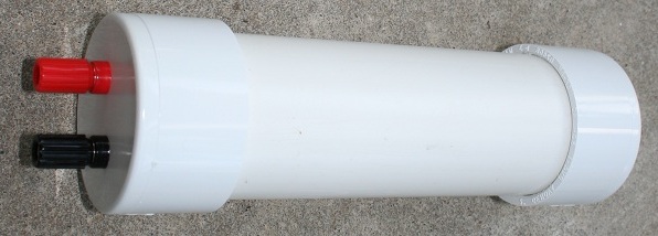
SLF Band antenna offers high sensitivity and narrow bandwidth.
Directional to help reduce interference and zero-in on desired signal.
Weather-proof plastic case.
Binding post connections.
Monster-size 12.3 inch long x 1.02 inch diameter ferrite rod core for maximum reception.
Part Number: 12SLF30H300HBC is an Extremely Low Frequency antenna for 30 Hz - 300 Hz range, and can be user tuned with external fixed value capacitor user supplies.
Specification: (+/- 10 %) 0.01 uF tunes @ 300 Hz.
NOTE:12SLF30H300H Antennas are 14 inches long and has a 12.3 inch x 1.02 inch ferrite core.
NOTE:24SLF30H300H Antennas are 24 inches long and has a 22.5 inch x 1.02 inch ferrite core.
NOTE:36SLF30H300H Antennas are 36 inches long and has a 34 inch x 1.02 inch ferrite core.
| Part # | Frequency | Price |
|---|---|---|
| 12SLF30H300HBC | 30 Hz - 300 Hz | $ 275.00 |
| 12SLF30H300HBC-EB | 30 Hz - 300 Hz | $ 285.00 |
| 24SLF30H300HBC | 30 Hz - 300 Hz | $ 395.00 |
| 36SLF30H300HBC | 30 Hz - 300 Hz | $ 495.00 |
NOTE: These antennas are bi-directional having a 'figure 8' pattern.

The 12SLF30H300HBC antenna is also available with EyeBolt loop [ EB suffex on part number ] to allow suspending the antenna above a magnet to make a simple yet powerful seismograph.
SLF Band antenna offers high sensitivity and narrow bandwidth.
Directional to help reduce interference and zero-in on desired signal.
Weather-proof plastic case.
Binding post connections.
Monster-size 12.3 inch long x 1.02 inch diameter ferrite rod core for maximum reception.
Part Number: 12SLF1H125HBC is an Extremely Low Frequency antenna for the 1 Hz - 125 Hz range, and can be user tuned with external fixed value capacitor user supplies.
If this antenna is used in a moving vehicle and connected to a millivolt meter, the meter will indicate strongly when the antenna passes over a buried iron pipe line or other metal under a roadway when moving at highway speeds. Signals over 1 volt can be generated depending on the strength of the magnetism in the buried metal.
Makes an excellent magnetic seismograph sensor pickup for 1 Hz - 5 Hz.
Use it to detect people walking thru a door via the magnetic metals and magnets contained in their cellphones, belt-buckles, etc.
Specification: (+/- 10 %), 22 uF tunes @ 1 Hz, 10 uF tunes @ 4 Hz, 3.3 uF tunes @ 7.5 Hz, 0.47 uF tunes @ 19 Hz, 0.33 uF tunes @ 23 Hz, 0.22 uF tunes @ 28 Hz, 0.1 uF tunes @ 43 Hz, 0.01 uF tunes @ 125 Hz.
NOTE: 12SLF1H125HBC Antennas are 14 inches long and has a 12.3 inch x 1.02 inch ferrite core.
NOTE: 24SLF1H125HBC Antennas are 24 inches long and has a 22.5 inch x 1.02 inch ferrite core.
NOTE: 36SLF1H125HBC Antennas are 36 inches long and has a 34 inch x 1.02 inch ferrite core.
| Part # | Frequency | Price |
|---|---|---|
| 12SLF1H125HBC | 1 Hz - 125 Hz | $ 285.00 |
| 12SLF1H125HBC-EB | 1 Hz - 125 Hz | $ 295.00 |
| 24SLF1H125HBC | 1 Hz - 125 Hz | $ 395.00 |
| 36SLF1H125HBC | 1 Hz - 125 Hz | $ 495.00 |
The 12SLF1H125HBC antenna is also available with EyeBolt loop [ EB suffex on part number ] to allow suspending the antenna above a magnet to make a simple yet powerful seismograph.
NOTE: These antennas are bi-directional having a 'figure 8' pattern.
20 Hz - 200 Hz

For use in
Antennas in this range are useful for specialized remote sensing applications.
Directional to help reduce interference and zero-in on desired signal.
These antennas feature a Mu-Metal Core for stable performance.
These antennas offer narrow band (high Q) tuning.
Research applications include: Geophysics, Meteorology, Mineral Exploration, etc.
Antennas are cased in weather-proof PVC plastic with two binding post connections.
| SLF Antenna | ||||
| Part # | Radio Band | Low Freq | Hi Freq | __Price |
|---|---|---|---|---|
| MUF21-20H-200H-BC | Super Low Frequency | 20 Hz | 200 Hz | $ 395.00 |
TUNING DATA: MUF21-20H-200H-BC
3.3 uF = 16 Hz
2 uF = 22 Hz
1 uF = 31 Hz.
0.47 uF = 46 Hz
0.22 uF = 68 Hz
0.1 uF = 102 Hz
0.047 uF = 150 Hz
0.022 uF = 218 Hz
0 pF = 800 Hz
Click Here for Data Sheet. Part Number: MUF21-20H-200H-BC.
DC - 30 KHz Wideband Instrumentation Amplifier for use with these antennas.
S/H UPS ground extra.

This sensitive receiver uses one IC chip, the LM-741. Output is an AC voltage that can be sent to an analog volt meter or data logging volt meter. Makes an excellent seismograph when used with antennas rated to tune 1 Hz, such as our 12SLF1H125HBC-EB. We have other antennas that allow for tuning down to 0.03 Hz, depending on antenna tuning specifications. See our ELF antennas also.
PARTS:
IC1 = LM 741 OP Amplifier IC.
R1 = 22 K-ohms
R2 = 10 Meg ohms
R3 = 10 Meg ohms
R4 = 22 K-ohms
C1 = Tuning value needed to tune antenna to desired frequency.
C2 = 1 uF
C3 = 100 uF
Power the circuit with a 9 volt rechargable battery. The circuit will also work on a 6-volt or 12 volt lantern rechargable battery. Current draw is less than 2 mA for long battery life.
When the power is first turned ON, allow @ 30 seconds for all the capacitors to charge up before the receiver starts working.
If used as a seismograph (when used with antennas rated for 1 Hz) The circuit can drive analog volt meters back and forth when an earthquake is detected (see this link for plans).
Connect the output to a data logging volt meter or oscilloscope to allow making graphs of received SLF waveforms. See www.dataq.com for excellent PC data logger hardware and software.
Circuit modifications:If receiving well below 1 Hz, then change C2 to a higher value, such as 10 uF or 47 uF. This may cause circuit to need more time when first turned ON to begin working, up to 3 minutes or more.
C3 can be changed to as high as 4700 uF to pass extremely slow waveforms. Again changing this value will require more start up time when first turned ON, up to 3 minutes or more.
R1 should not be made less than 10 K-ohms.
If the circuit oscillates ( not likely ! ) then place a 100 uF across the battery terminals.

See our complete line of standard antennas:
Antennas for Short Wave 1.7 MHz - 4 MHz
Antennas for AM Broadcast Band 530 KHz - 1710 KHz
Antennas for Long Wave and 30 KHz - 530 KHz
Antennas for Very Low Frequency 3 KHz - 30 KHz
Antennas for Ultra Low Frequency 300 Hz - 3 KHz
Antennas for Super Low Frequency 30 Hz - 300 Hz
Antennas for Extremely Low Frequency 0.03 Hz - 30 Hz